KI-Beratung Beta

Gutscheinbedingungen

**Gültig bis 18.11.2026 auf englischsprachige Klassiker (klassiker-32728) online auf thaalia.live und in der Thalia App. Einzelne Artikel können ausgeschlossen sein. Ausgenommen sind preisgebundene Artikel & eBooks. Pro Einkauf einmal einlösbar. Click & Collect nur bei Onlinevorabzahlung möglich. Keine Barauszahlung. Nicht kombinierbar mit anderen Aktionen und Gutscheinen. Gutschein wird auf max. 500€ Bestellwert angerechnet. Nicht gültig für Geschenkkarten, Versandkosten und Services.

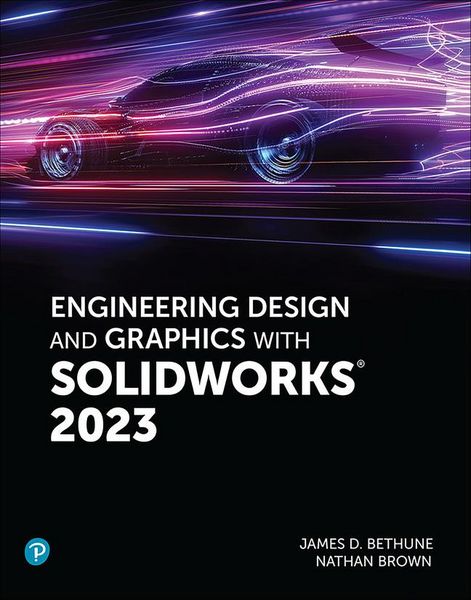
Produktbild: Engineering Design and Graphics with SolidWorks 2023

Engineering Design and Graphics with SolidWorks 2023

118,99 €

inkl. gesetzl. MwSt., Versandkostenfrei


Beschreibung

Engineering Design and Graphics with SolidWorks 2023 In Engineering Design and Graphics with SolidWorks 2023, award-winning CAD instructor and author James Bethune shows students how to use SolidWorks to create engineering drawings and designs. The textbook has been updated to cover the new features...

Beschreibung

Engineering Design and Graphics with SolidWorks 2023 In Engineering Design and Graphics with SolidWorks 2023, award-winning CAD instructor and author James Bethune shows students how to use SolidWorks to create engineering drawings and designs. The textbook has been updated to cover the new features in SolidWorks 2023. It focuses on the creation of engineering drawings, including dimensions and tolerances and the use of standard parts and tools. Each chapter contains step-by-step sample problems that show students how to apply the concepts presented in the chapter. Effective pedagogy throughout the text helps students learn and retain concepts: Objectives: Each chapter begins with objectives and an introduction to the material. Summaries: Each chapter concludes with a summary and exercise problems. Numerous Illustrations: The multitude of illustrations, accompanied by explanatory captions, present a visual approach to learning. Students see in the text what they see on the screen with the addition of explanatory text. Practical Application: The text provides hundreds of exercise projects of varying difficulty (far more than any other computer graphics text). These exercises reinforce each chapter's content and help students learn by doing. Flexibility: With the hundreds of problems presented in the book, instructors can assign different problems within the same class and from year to year without repeating problems for students. Meets Standards: The text teaches ANSI standards for dimensions and tolerances. This helps students understand how their designs are defined for production and the importance of proper tolerancing. Step-by-Step Approach: In presenting the fundamentals of engineering drawing using SolidWorks, the text uses a step-by-step approach that allows students to work and learn at their own pace  

Produktdetails

Einband

Taschenbuch

Erscheinungsdatum

07.04.2024

Verlag Pearson Academic
Seitenzahl

784

Produktdetails

Einband

Taschenbuch

Erscheinungsdatum

07.04.2024

Verlag Pearson Academic
Seitenzahl

784

Maße (L/B/H)

21,6/27,6/3,6 cm

Gewicht

1644 g

Auflage

1. Auflage

Sprache

Englisch

ISBN

978-0-13-789952-4

Herstelleradresse

Libri GmbH
Europaallee 1
36244 Bad Hersfeld
DE

Email: gpsr@libri.de

Noch keine Bewertungen vorhanden

Verfassen Sie die erste Bewertung zu diesem Artikel

Helfen Sie anderen Kundinnen und Kunden durch Ihre Meinung.

Kundinnen und Kunden meinen

Bewertungen (0)

Die Leseprobe wird geladen.
  • Produktbild: Engineering Design and Graphics with SolidWorks 2023
  • Preface
    Chapter 1 Getting Started
    Chapter Objectives
    1-1 Introduction
    1-2 Starting a New Document
    1-3 SolidWorks Colors
    1-4 Creating a Fully Defined Circle
    1-5 Units
    1-6 Rectangle
    1-7 Moving Around the Drawing Screen
    1-8 Orientation
    1-9 Sample Problem SP1-1
    1-10 Creating 3D Models
    1-11 Saving Documents
    1-12 Sample Problem SP1-2
    1-13 Holes
    Chapter Project
    Chapter 2 Sketch Entities and Tools
    Chapter Objectives
    2-1 Introduction
    2-2 Mouse Gestures and the S Key
    2-3 Origins  
    2-4 Circle  
    2-5 Rectangle  
    2-6 Slots  
    2-7 Perimeter Circle  
    2-8 Arcs  
    2-9 Polygons  
    2-10 Spline  
    2-11 Ellipse  
    2-12 Fillets and Chamfers  
    2-13 Sketch Text
    2-14 Point  
    2-15 Trim Entities  
    2-16 Extend Entities  
    2-17 Offset Entities  
    2-18 Mirror Entities  
    2-19 Linear Sketch Pattern  
    2-20 Circular Sketch Pattern  
    2-21 Move Entities  
    2-22 Copy Entities  
    2-23 Rotate Entities  
    2-24 Scale Entities  
    2-25 Stretch Entities  
    2-26 Split Entities  
    2-27 Jog Lines  
    2-28 Centerline  
    2-29 Sample Problem SP2-1
    2-30 Sample Problem SP2-2
    2-31 Sample Problem SP2-3
    Chapter Projects
    Chapter 3 Features
    Chapter Objectives
    3-1 Introduction
    3-2 Extruded Boss/Base
    3-3 Sample Problem SP3-1  
    3-4 Extruded Cut  
    3-5 Hole Wizard 3-6 Creating a Hole with the Circle and Extruded Cut Tools  
    3-7 Blind Holes  
    3-8 Fillet  
    3-9 Chamfer  
    3-10 Revolved Boss/Base  
    3-11 Revolved Cut  
    3-12 Reference Planes  
    3-13 Lofted Boss/Base  
    3-14 Shell  
    3-15 Swept Boss/Base  
    3-16 Draft  
    3-17 Linear Sketch Pattern  
    3-18 Circular Sketch Pattern  
    3-19 Mirror  
    3-20 Helix Curves and Springs  
    3-21 Compression Springs  
    3-22 Torsional Springs  
    3-23 Extension Springs  
    3-24 Wrap  
    3-25 Editing Features  
    3-26 Sample Problem SP3-2  
    3-27 Sample Problem SP3-3
    3-28 Curve Driven Patterns
    Chapter Projects
    Chapter 4 Orthographic Views
    Chapter Objectives
    4-1 Introduction
    4-2 Third- and First-Angle Projections
    4-3 Fundamentals of Orthographic Views
    4-4 Drawing Orthographic Views
    4-5 Section Views  
    4-6 Drawing a Section View  
    4-7 Aligned Section Views  
    4-8 Broken Views  
    4-9 Detail Views  
    4-10 Auxiliary Views  
    4-11 First-Angle Projection
    Chapter Projects
    Chapter 5 Assemblies
    Chapter Objectives
    5-1 Introduction
    5-2 Starting an Assembly
    5-3 Move Component
    5-4 Rotate Component
    5-5 Mouse Gestures for Assemblies
    5-6 Mate  
    5-7 Bottom-up Assemblies  
    5-8 Creating an Exploded Isometric Assembly  
    5-9 Creating an Exploded Isometric Drawing  
    5-10 Assembly Numbers  
    5-11 Bill of Materials (BOM or Parts List)  
    5-12 Title Blocks  
    5-13 Animate Collapse  
    5-14 Sample Problem SP5-1  
    5-15 Using the Motion Study Tool  
    5-16 Editing a Part Within an Assembly 5-17 Interference Detection/ClearanceVerification  
    Chapter Projects  
    Chapter 6 Threads and Fasteners
    Chapter Objectives
    6-1 Introduction
    6-2 Thread Terminology
    6-3 Thread CalloutsANSI Metric Units
    6-4 Thread CalloutsANSI Unified Screw Threads
    6-5 Thread Representations
    6-6 Internal ThreadsInches
    6-7 Threaded Blind HolesInches
    6-8 Internal ThreadsMetric
    6-9 Accessing the Design Library  
    6-10 Thread Pitch 6-11 Determining an External ThreadLengthInches  
    6-12 Smart Fasteners  
    6-13 Determining an Internal Thread Length  
    6-14 Set Screws 6-15 Drawing a Threaded Hole in the Sideof a Cylinder  
    6-16 Adding Set Screws to the Collar  
    Chapter Projects  
    Chapter 7 Dimensioning
    Chapter Objectives
    7-1 Introduction
    7-2 Terminology and ConventionsANSI
    7-3 Adding Dimensions to a Drawing
    7-4 Drawing Scale
    7-5 Units
    7-6 Dimensioning Holes and Fillets
    7-7 Dimensioning Counterbored and Countersunk Holes
    7-8 Angular Dimensions
    7-9 Ordinate Dimensions
    7-10 Baseline Dimensions
    7-11 Locating Dimensions
    7-12 Fillets and Rounds
    7-13 Rounded ShapesInternal  
    7-14 Rounded ShapesExternal  
    7-15 Irregular Surfaces  
    7-16 Polar Dimensions  
    7-17 Chamfers  
    7-18 Symbols and Abbreviations  
    7-19 Symmetrical and Centerline Symbols  
    7-20 Dimensioning to a Point  
    7-21 Dimensioning Section Views  
    7-22 Dimensioning Orthographic Views  
    Chapter Projects
    Chapter 8 Tolerancing
    Chapter Objectives  
    8-1 Introduction  
    8-2 Direct Tolerance Methods  
    8-3 Tolerance Expressions  
    8-4 Understanding Plus and Minus Tolerances  
    8-5 Creating Plus and Minus Tolerances Adding Plus and Minus Symmetric Tolerances Using the Dimension Text Box  
    8-6 Creating Limit Tolerances  
    8-7 Creating Angular Tolerances  
    8-8 Standard Tolerances  
    8-9 Double-Dimensioning Errors 8-10 Chain Dimensions and Baseline Dimensions  
    8-11 Tolerance Studies  
    8-12 Rectangular Dimensions  
    8-13 Hole Locations  
    8-14 Choosing a Shaft for a Toleranced Hole  
    8-15 Sample Problem SP8-1  
    8-16 Sample Problem SP8-2  
    8-17 Nominal Sizes  
    8-18 Standard Fits (Metric Values)  
    8-19 Standard Fits (Inch Values)  
    8-20 Preferred and Standard Sizes  
    8-21 Surface Finishes  
    8-22 Surface Control Symbols  
    8-23 Applying Surface Control Symbols  
    8-24 Design Problems  
    8-25 Geometric Tolerances  
    8-26 Tolerances of Form  
    8-27 Flatness  
    8-28 Straightness  
    8-29 Straightness (RFS and MMC)  
    8-30 Circularity  
    8-31 Cylindricity  
    8-32 Geometric Tolerances Using SolidWorks  
    8-33 Datums  
    8-34 Tolerances of Orientation  
    8-35 Perpendicularity  
    8-36 Parallelism  
    8-37 Angularity  
    8-38 Profiles  
    8-39 Runouts  
    8-40 Positional Tolerances  
    8-41 Creating Positional Tolerances  
    8-42 Virtual Condition  
    8-43 Floating Fasteners  
    8-44 Sample Problem SP8-3  
    8-45 Sample Problem SP8-4  
    8-46 Fixed Fasteners  
    8-47 Sample Problem SP8-5  
    8-48 Design Problems  
    Chapter Projects  
    Chapter 9 Bearings and Fit Tolerances
    Chapter Objectives
    9-1 Introduction
    9-2 Sleeve Bearings
    9-3 Bearings from the Toolbox
    9-4 Ball Bearings
    9-5 Fits and Tolerances for Bearings
    9-6 FitsInches
    9-7 Clearance Fits
    9-8 Hole Basis
    9-9 Shaft Basis
    9-10 Sample Problem SP9-1
    9-11 Interference Fits
    9-12 Manufactured Bearings
    9-13 Fit TolerancesMillimeters
    Chapter Projects
    Chapter 10 Gears
    Chapter Objectives
    10-1 Introduction
    10-2 Gear Terminology
    10-3 Gear Formulas
    10-4 Creating Gears
    10-5 Gear Ratios  
    10-6 Gears and Bearings  
    10-7 Power TransmissionShaft to Gear  
    10-8 Set Screws and Gear Hubs  
    10-9 Keys, Keyseats, and Gears
    10-10 Sample Problem SP10-1
    10-11 Rack and Pinion Gears  
    10-12 Metric Gears  
    Chapter Projects
    Chapter 11 CSWA Preparation
    Chapter Objectives
    11-1 Introduction
    11-2 Working with Cubes
    11-3 Drawing Profiles
    11-4 Drawing Small 3D Objects
    11-5 Drawing Larger Objects
    11-6 Drawing Auxiliary Views
    11-7 Drawing Break Views
    11-8 Drawing Section Views
    11-9 Drawing Detail Views
    11-10 Drawing Lines and Views
    11-11 Creating Assemblies
    11-12 Problem Answers
    Appendix

    9780137899524    TOC    2/2/2023